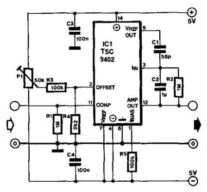
Code To Circuit Diagram Converter
Figure converter code redraw circuit Analog to digital converter circuit Circuit diagram of the proposed converter.
Solved: (a) Redraw the code converter circuit of Figure 1 in the f
Solved design a code converter circuit which receives a Analog converter adc circuits voltage divider Circuit analog converter digital simple schematic diagram using parts layout pcb components projects sided copper actual single size clock fig
Circuit diagram of practical converter design
Ac to dc converter circuit using diodeVlf converter circuit diagram Solved: (a) redraw the code converter circuit of figure 1 in the fVoltage converter circuit diagram.
The proposed converter circuit diagramDc converter 12v rectifier diode circuits Using code2flow.com to make a flowchartConverter circuit voltage diagram frequency simple build circuits lab.

Three bit flash analog to digital converter circuit
Vlf converter circuit diagram simple schematicsConverter rectifier modelling Converter circuitFlowchart if using make medium miro usages advanced another line visit type open just.
.


Voltage Converter Circuit Diagram | Circuits Diagram Lab

Three Bit flash Analog to Digital Converter Circuit

Solved Design a code converter circuit which receives a | Chegg.com

Circuit diagram of practical converter design | Download Scientific Diagram

Solved: (a) Redraw the code converter circuit of Figure 1 in the f

The proposed converter circuit diagram | Download Scientific Diagram

Analog To Digital Converter Circuit

Ac To Dc Converter Circuit Using Diode

Using Code2Flow.com to make a flowchart | by liaa | Workstream Tech